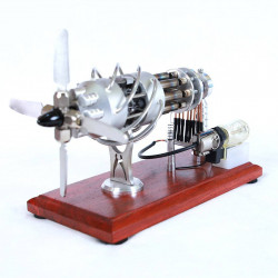
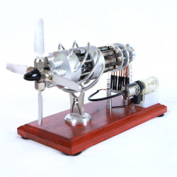
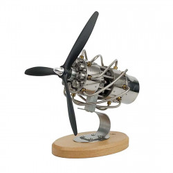
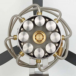
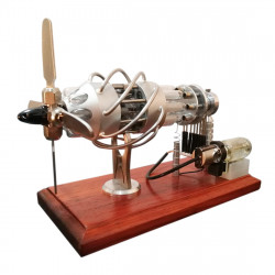
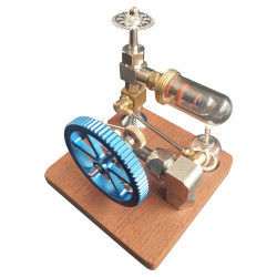
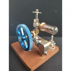
What is Stirling engine
A Stirling engine uses air or gas to create energy by compressing and expanding it at different temperatures."
To be more precise, the Stirling engine is a permanently gaseous closed-cycle regenerative heat engine. In this case, "closed-cycle" means the working fluid stays inside the system. "Regenerative" refers to using a special internal temperature exchanger called a regenerator. What sets a Stirling engine apart from other closed-cycle heat engines is the presence of a regenerator.
People used steam engines in many real-world applications in the early nineteenth century. They were still flawed, though, in a lot of ways.
Boilers were one issue in particular; they had a propensity to blow up, injuring and killing people. Scottish pastor Reverend Dr. Robert Stirling was worried about the number of people killed by boiler explosions. In 1816, Stirling applied for a patent for a safer engine. He based his design on the groundbreaking work of George Cayley, who was a prominent figure in aeronautics.
Of all thermal engines, the Stirling engine has the highest theoretical efficiency. Additionally, the machine is fundamental. In contrast to other engine types, the absence of valves dramatically simplifies the mechanical design.
Principles of a Stirling Engine
A Stirling engine, similar to other engines, has two areas that control temperature. In these areas, work is done by moving the fluid inside the engine." The power piston is located in the blue-colored cold zone on the right in the animation. The displacer piston is in the hot zone, indicated in red.
When more heat is introduced to the hot zone, the gas expands and pushes the power piston, creating work.
The displacer moves left, transferring gas from hot to cold zone as power piston finishes its stroke. The power piston shifts to the left as the gas cools and shrinks. The cycle then starts over.
There are two basic configurations of a Stirling engine. The alpha type is shown on the left. The beta type was discussed earlier. The working principle is the same.
The alpha engine moves gas between its two power piston cylinders, which connect at the same position in the crankshaft. Situated between the hot and cold zones, the regenerator functions as a heat exchanger and is a fundamental element of the 1816 invention.
Thermal efficiency is raised by the regenerator's retention of heat that would otherwise be lost to the surroundings. Several design versions employ the Stirling cycle, including:
- the rotary displacer type,
- the low-temperature differential or LTD,
- the fluid engine,
- the thermoacoustic engine,
- the marble engine,
- multiple piston engines.
Waiting for Material Science to Catch Up
With the help of his engineer brother James, Stirling improved the design. They built and marketed their engines as a steam engine substitute.
However, high temperatures are required for the Stirling engine to function at its peak efficiency and power output. There were many failures in the early years because the materials were not up to the task. The steam engine improved and grew safer during the same period.
Additionally, stirlings were significantly more significant than a steam engine with the same power. As a result, they lost ground to rivals like steam and the recently developed internal combustion engine.
Stirling engines had limited uses for low-power applications, such as providing air supply for church organs, pumping water, and operating ventilators. However, the electric motor finally replaced the technology in even these applications.
Many engine difficulties were resolved when steel was developed, but it was too late. In 1876, Stirling said that Bessemer's genius and time have helped to fix these imperfections.
It is likely that the air engine would have been successful. This would have been the case if Bessemer iron or steel was available 35 or 40 years ago. In the future, skilled and motivated mechanics will need to replicate it perfectly under the right conditions.
Stirling Engine Electric Generator and Cryocooler
Thanks to the Phillips Research Laboratory in Eindhoven, engine development continued until the mid-1930s. Phillips wanted a tiny, silent, thermally driven electric generator for outlying areas to increase sales of its tube radios. While they successfully produced a 200-watt Stirling engine generator in 1951, the device's cost could have been more competitive.
Transistor radios had only been introduced by then. They required very little power; thus, batteries could power them, negating the need for the Stirling generator.
On the other hand, Phillips' research yielded a plethora of new information for the Stirling engine's continued development. They created a cryocooler concurrently, the only Stirling engine application that has succeeded commercially.
When the shaft undergoes mechanical work, the engine operates in reverse and generates a temperature differential. It can reach -200 C, a temperature low enough to melt air.
Stirling in Automotive
The Stirling engine was being developed for use in automobiles. Modern car engines have a 20–25% thermal efficiency range, while the MOD II project created an engine with a 38.5% thermal efficiency in 1986.
When tested in a Chevrolet Celebrity notchback, the engine's urban fuel economy was raised from 26 to 33 mpg. The startup time of about thirty seconds was one drawback. Ford, however, created a version that could start the engine in seconds thanks to internal heaters. The development of an automobile, Stirling, was stopped because of funding cuts and a lack of interest from automakers.
Finding Its Niche
The Stirling engine finds usage in a few additional specialized applications in addition to cryocoolers. An alternating magnetic field drives the piston, creating a temperature differential in the free-piston Stirling engine (FPSE). The unit can be fully sealed because the magnetic drive eliminates the need for gaskets and seals. NASA uses it to cool satellite instrumentation because of its outstanding reliability.
Desalination systems, like Dean Kamen's invention, the Slingshot, which employs water vapor distillation to purify water, are examples of potential future applications. Any fuel can power its Stirling engine. Stirling engines are being tested in solar power by electric generators focused on parabolic mirrors. The efficiency is higher with this configuration than it is with non-concentrated photovoltaics.
Some suggest replacing steam turbines in nuclear power plants to eliminate the need for water in the system. A Stirling engine uses nuclear fuel to generate heat and can operate for long periods of time during space exploration.
A fascinating concept for residential use has gained traction in recent years: micro-combined heat and power, a technology that allows individual dwellings to produce heat and electricity from the same energy source. This fossil fuel-powered generator is engine-driven and linked to the grid. Using a heat exchanger generates electricity and uses waste heat to heat water.
We have good news for anyone interested in experimenting with Stirling engines: they are among the easiest to construct. It's still being determined if the Stirling will continue to be used in specialized applications or will ever play a significant part in the engine industry after 200 years. Without a doubt, we aim for the first.
What are the Uses for Stirling engines?
1, Cogeneration (CHP)- A Stirling engine in a cogeneration unit can use waste heat resulting from the second law of thermodynamics. This waste heat can power the Stirling engine for industrial or agricultural activities.
2, Solar energy generation- Stirling engines, as shown in the figure below, can convert sun power into electricity more efficiently than some photovoltaic cells when placed at the primary of a parabolic mirror.
3, Submarines- Submarines with Stirling engines have a significantly longer submersion time than regular submarines. The first submarine to use Stirling engines was built by the Swedish shipbuilder Kockums. These engines allow a submarine to submerge for more extended periods—days or even weeks—without having to surface to replenish its batteries.
Nuclear power plants: Stirling engines can replace steam turbines in nuclear reactors, improving plant efficiency and lowering the amount of radioactive byproducts. These would eliminate the need for water at any point in the cycle and replace it with liquid sodium as a coolant.
4, Educational demonstration- a slight temperature variation A stirling engine can operate at any low-temperature differential, such as the one between a hand's palm and palm, as shown in Figure 4. (A Low-Temperature Difference (LTD) Stirling engine may produce around 1 W of power directly from a person's palm.)
What are the different types of Stirling engine model?
Their working space shows that stirling engines can be divided into alpha, beta, and gamma.
What is the Alpha Stirling engine?
Two power pistons—one hot and one cold—are housed in separate cylinders in an alpha Stirling.
How does a Stirling engine work?
A thermodynamically "closed" regenerative cycle powers the Stirling engine. It operates at various temperature levels using the working fluid's cyclical expansion and compression.
A gas goes through a compression and expansion cycle known as the Stirling cycle. It functions by causing a gas to expand and compress. Using two temperature settings, thermal energy is netly converted into mechanical work.
The Stirling engine is conventionally categorized as an external combustion engine, just like the steam engine. The engine wall facilitates all heat transfers with the working gas. In contrast to internal combustion engines, it gets its heat from an external source.
In contrast to a steam engine, the Stirling engine shuts off a specific volume of fluid in a permanently gaseous condition, like air. On the other hand, the working fluid in a steam engine changes phases from liquid to gas.
The displacer cylinder is where the pressure variation happens. In the cold zone is the displacer. The flywheel and crankshaft are rotated by the heat generated at this moment. This is how heat energy creates mechanical energy.
The Carnot cycle's efficiency severely limits the process's overall efficiency. The Carnot cycle states that the temperature differential between the hot and cold tanks determines efficiency.
Build A Small Beam Stirling Engine
Step 1: Cylinder
Round brass bar squares are first filed in order to create the cylinder. Indexing the bar in the headstock and maintaining the file's horizontal position with two rollers is a simple method. As an alternative, you may start with square stock.
You can choose the cooling fins' profile; in this case, they are rounded, but they can alternatively be left square. As seen below, a slitting saw or parting tool revolving in the opposite direction from the workpiece can be used to cut the fins.
On one side of the cylinder, an endmill is used to cut the recess that will hold the hot cap (which will be seen later). For the reciprocating rod attached to the displacer piston, a 1mm hole needs to be drilled on the other side.
Parting the cylinder off is followed by installing it in a collet the other way around and tapping the bottom with an M2 thread so that it may be bolted to a base plate.
Step 2: Displacer Piston
This part is composed of aluminum since it is best practice to make reciprocating components as light as feasible. To allow air to circulate around the outside, the displacer is purposefully built to fit loosely inside the hot cap. To accommodate the 1 mm diameter reciprocating rod, an M1 thread is tapped into one end of the displacer.
To lower the displacer's drag coefficient, a point is machined onto the other end.
Step 3: Power Piston
The main cylinder must precisely fit the power piston. The power piston must have free motion, yet this fit must be gas-tight.
Silver steel with a 3mm diameter is used to machine this item. The gudgeon pin will be inserted into the perpendicular hole, and a slot is cut at the end for the con rod to fit later.
In addition to polishing the surface and eliminating burrs, a sapphire burnishing tool also offers the advantage of hardening the surface.
Step 4: Central Pillar
The beam The horizontal beam that joins the power piston and flywheel defines a Stirling engine. In order to reach the central pillar, this beam must pivot around a point.
First, the pillar is polished and turned with a small taper. The beam's pivot point and slit are made with a drill bit and slitting saw. To guarantee a satisfactory fit with a tapered pin, the hole is cross-drilled to 0.7 mm and will subsequently be expanded up using a tapered broach during assembly.
A section close to the pillar's base must be milled away in order to provide room for a reciprocating fitting. A slot is machined perpendicular to this feature so that the rod connecting the flywheel and displacer can later pass through.
Lastly, a thread is cut in the pillar's base and the component is turned around in the collet.
Step 5: Bearing Housing
The flywheel is supported by two small 1.5mm ID ball races that are housed in the bearing housing. The bearing housing's two faces are filed parallel using the same procedure as the cylinder. For these bearings, an endmill is used to cut the hole.
Before the housing is separated from the bar stock, its top is filed round. A thread is cut in the part's base for mounting to the base plate, and it is mounted in the collet the other way around.
Using a tiny vice, the ball races are pressed into place for a tight press fit.
Step 6: Hot Cap
The component that receives heat to power the engine is called the hot cap. Because of its limited heat conductivity, stainless steel is the perfect material to maximize the temperature differential between the cylinder and this portion.
Drilling and then boring a hole in the stock creates the thin wall of the hot cap. After that, it is separated and turned around in the chuck so that the closed end faces out.
Step 7: Printing, Casting and Machining the Flywheel
A simpler flywheel with machineable flat spokes would undoubtedly allow you to bypass most of these processes, but this seemed like a nice chance to illustrate the investment casting process.
First, a CAD model of the flywheel is created. After some testing, we chose to include a stub and some sturdy support in the model at this point instead of relying on the slicing software to provide the support.
We used the following parameters in Photon Workshop to slice the STL because we have an Anycubic Photon resin printer. (As you can see, in order to have a spare, we produced two flywheels simultaneously.)
- Layer thickness: 0.05 mm
- Normal exposure time: 21 s
- Bottom exposure time: 80 s
- Bottom layers: 5
- Z lift speed: 0.5 mm/s
After finishing, the print is gently taken off the bed and cleaned and cured just like any other print.
To create a channel for the molten metal to pass through during casting, a number of wax sprues are applied to the model using a soldering iron. The model is then mounted into a flask and filled with investment slurry.
N.B. When using investment powder, always wear a suitable mask - the silica particles can cause serious lung damage if inhaled.
The slurry is created by combining the powder and water. Air bubbles are inevitable since the mixing process agitates the mixture. By degassing the slurry in a vacuum chamber, these can be eliminated.
After pouring the liquid into the flask with the 3D-printed flywheel, the flask is left for a few hours to allow the slurry to cure.
The rubber flask base can be peeled off after it has dried. Now that ceramic has encased the wax geometry, it may be melted out in a furnace. A series of temperature ramps up to 730 °C are utilized, commencing at 120 °C. This melts the wax, burns off any leftover residue, and completely cures the investment mixture.
In order to pour the molten metal into what should now be a flywheel-shaped chamber, the flask is taken out of the furnace at about 650°C. To assist in sucking the metal into the mold cavity, the hot flask is positioned over a hole in the vacuum chamber. In parallel, a blowtorch is used to melt some brass in a crucible. The brass is poured into the top of the mold once it is fully melted.
The mold is broken apart and the casting is released when the flask and mold are quenched in water. A mixture of hand tools, machining, and milling can be used to eliminate superfluous material after the casting has been inspected for flaws. In the watchmakers' lathe, leaving the middle stub oversized creates a handy surface for holding the flywheel.
The flywheel can now be completed with a 1.5 mm hole bored in the center for the main shaft and some lighter cuts made on the watchmaker's lathe.
Although painting is obviously optional, red enamel paint was used to color the flywheel's spokes.
Step 8: Base Plate
A little piece of flat brass is used to create a foundation plate because all the parts must be secured in place. This part's external shape isn't very significant, but the holes' relative locations must be exact. Coordinate drilling using a DRO is a simple method to get this right, although hand measurement would also work well.
Step 9: Con Rods, Beams and Pins
The titanium shim used to make the beam and con rods is thin enough to be cut with scissors. A tiny high-speed drill is used to drill the holes, and a needle file is used to round the corners.
Tapered pins with a diameter of 0.8 mm are used to secure the beam and connecting rods in position. Short lengths of piano wire are used to make these. A diamond stone and burnisher are used to apply a small taper after each component has been faced off and deburred in the lathe.
Since there isn't enough metal to press fit a tapered pin here, a different method was needed for the pin that connects two con rods. To prevent it from falling out, this pin is cross-drilled with a 0.4 mm tapered pin.
Step 10: Crank
The crank is made up of a tiny pin and a metal ring with a radially threaded screw. Because of the 1.5 mm offset of the pin, the piston stroke is 3 mm.
Step 11: Assembly and Testing
First, the baseplate is fitted with the three major parts. If desired, the main pillar might be mounted in the same manner as the cylinder and bearing housing, but it is threaded into the end of a pencil here.
A little screwdriver is used to fasten the crank onto the flywheel axle.
The piston, which is located inside the cylinder, is lubricated with a dab of watch oil. After that, the connecting rods and beam are installed. The displacer con rod goes through the slot in the pillar, and the displacer is inserted into the other cylinder recess.
The hot cap is a straightforward press-fit into the cylinder's endmill-machined depression.
Testing to see if the engine runs over a tiny flame is, of course, the last stage.
I appreciate you reading!
