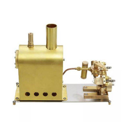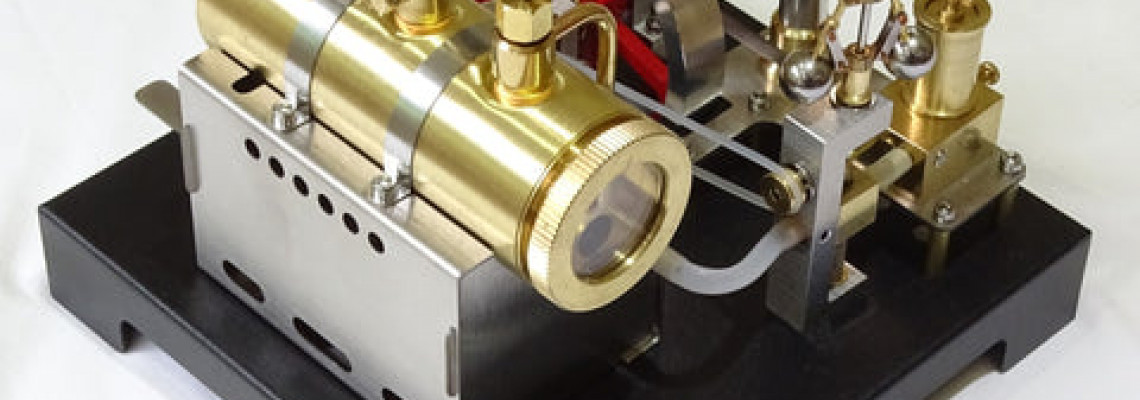
DETAILED REVIEW RETROL Model Beam Steam Engine Kit and Horizontal Boiler with Flyball Regulator
The Retro Beam Engine and Boiler kit is wholly machined and requires just essential tools to assemble into a functional model steam plant. In reality, it consists of several subassemblies of parts rather than a kit of separate parts. Although this lessens the possible enjoyment of constructing the steam plant, it can aid a total beginner in modeling engineering.
The first impression upon opening the package is that, despite its modest size, this high-quality beam engine and boiler kit is well-presented, especially considering its low cost (about £250 at the time of writing, depending on delivery options). It does, however, include some poorly designed and manufactured parts that will lessen the enjoyment of ownership. I wouldn't advise a youngster or total beginner to buy it because of the burner in particular.
A seasoned model engineer could make corrections or devise workarounds, but most would prefer something more difficult, more realistic in appearance, with fewer financial concessions, and the opportunity to develop something entirely original.
With a few exceptions, primarily because of the burner, the engine and boiler function effectively when operating on steam.
Introduction
The Chinese website V8engineforsale serves as an online store for several Chinese model engine manufacturers' brands, including Musa and Retrol. Over the past few years, I have purchased several of these products, some of which are excellent and many of which require correction because insufficient time was spent on the final prototype prior to full production.
In May 2024, V8engineforsale contacted me to provide an unbiased assessment of their latest offering, the Beam Engine and Boiler model steam plant kit.
Retrol/V8engineforsale might note my observations and fix them, but it's safest to presume that they've already produced a sizable batch; thus, an updated version will be available soon.
Retrol has obviously invested in high-quality packaging and lustrous documentation sheets, which are fantastic to display to clients in a retail setting. With the exception of the fuel, all the parts, equipment, etc., required to assemble and run the engine are included.
General Assembly
There is a graphic on the construction sheets that discusses some safety issues, but more instructions are needed regarding safety, including avoiding leaving small children unattended, hazardous flames,
carbon monoxide risk, proper fuel handling, etc.
The step-by-step assembly instructions are sketches instead of actual images, which are good but frequently lack necessary supplemental information. The picture of numbered components is included, but there are no part names, which is crucial for learning purposes. For instance, instead of just referring to "part 3," include a table naming it the Connecting Shaft; similarly, "part 7" refers to the Cylinder and Chest Subassembly.
Step-by-Step Assembly Observations
Taking each of the assembly sheet steps, in turn, these are my observations;
1. I don't understand how the chest and Cylinder (part 7) are attached. Neither screws nor solder residue are present. If the parts were just glued together, I would be worried about how long they would stay together. Note that at this point, the retaining screws should be left a little loose.
2. The mounting plate's holes allow the retaining screws for the components in step 1 to be accessed, which is convenient for later fine-tuning. It is important to note that at this time, the nuts and screws holding the Main Bearing Pedestals (parts 11) in place should be left somewhat free.
3. It is unfortunate that the beam, shaft, piston, Watts parallel motion, etc. (part 1) is supplied as a finished subassembly. It would have been incredibly satisfying to put all these parts together.
The absence of a piston ring is disappointing because strong nylon would significantly reduce steam leaks while causing little drag.
4. The roller bearings (part 18), which ought to press fit into the central bearing pedestals, are too loose.
5. As previously stated, it is unfortunate that the eccentric rod, crank, valve, etc. (part 12) are supplied as a subassembly rather than as individual components. An essential educational point is that the Eccentric/Valve regulates the steam flow into the Cylinder, which is critical to the functioning of a steam engine.
6. Since it is challenging to assemble on the shaft, it is good that the grub screw is already put into the flywheel hub (part 4). The flywheel is composed of aluminum; a larger, heavier flywheel made of steel or aluminum would enable the engine to operate more slowly, which is more aesthetically pleasing for a beam engine. The flywheel wobbles noticeably, which I know many people will find unacceptable.
7. To ensure extremely smooth rotation, the screws for the Bearing Pedestals (part 11) must be gradually tightened while the flywheel is rotating. To keep them in place, the Pulley Wheel (part 16), Spacer (part 15), and Eccentric Wheel (part 12) should also be pushed up to the Main Bearings. The Spacer looks to wobble on the Crank Shaft because the interior bore is drilled out a little too large (part 14).
8. Because the crankpin (part 10) has a left-hand thread, the diagram does instruct screwing it anticlockwise. This is acceptable, but it would have been simple to construct the engine to run in the opposite direction; therefore, a regular thread could have been used. In order to prevent binding, the remaining screws should be gradually tightened while the flywheel is rotating. Since most moving parts fit loosely, it should be simple to achieve highly free movement with caution. Any tightness will consume steam pressure.
9. Like the previous comment, it would have been preferable to construct the Fly-ball governor/regulator (part 17) from individual components as opposed to relying solely on a bolt on a subassembly. Although the bearings holding the regulator's shaft are incredibly loose, it appears like the parts are bonded together, making it impossible to tighten them up by pressing them together. Though they keep the price cheap, I don't like the silicon tubes (parts 35). The design should at least be changed to ensure that the brass tubes line up precisely (they are about 1mm out). To allow the regulator valve to travel up and down freely, the longer screws (part 23) should be gradually tightened.
10. I used air pressure to test the boiler before proceeding with the assembly. The boiler maintained most of that pressure for a few minutes, preventing any significant leaks. The safety pressure valve released at about 20 psi, which is acceptable as the most pressure I would risk in this configuration.
11. Parts 29 through 33 of the boiler support/mount fit together well.
12. The boiler was easy to install in its mount.
13. Once more, leave the screws loose until everything is in position, then tighten them, just like you did with the Boiler Bands (part 32).
14. The regulator's brass pipe connecting to the boiler is far too short. To keep the silicon connecting tube straight and only bridging a small distance, I would advise that the brass pipes connecting the regulator to the boiler be sufficiently long, aligned, and bent to be close to one another. It would be less expensive to produce, look nicer, and be more secure.
15. Parts 36, 37, and 38 of The Burner are simple to put together, however...
16. According to the instructions, 95% alcohol is used as fuel for the burner. During the 1960s and 1970s, methylated spirits—also known as meths or denatured alcohol—powered a variety of steam engines, including Mamods. When fuel tablets were controlled in the UK, solid fuel tablets and, more recently, fuel gel replaced this for safety concerns.
In order to use fuel gel, the burner should be modified. For more information, see Forest Classics at https://www.forest-classics.co.uk/wilesco/wilesco-spares/gel-fuel-250-ml. First and foremost, I would suggest swapping out the supplied alcohol/meth burner for an open-pan fuel gel burner, which would be less expensive to produce and safer to use.
As previously said, additional safety instructions are needed, such as warning against leaving young children unattended, preventing burns from fires, handling fuel, the danger of carbon monoxide, etc., as these things are not immediately apparent to a beginner.
Although it's a good idea, the tank/tray (part 27) that collects the engine's condensed steam is too high to slide under the base simply.
Operating the Engine
When operating the boiler and engine, the following observations were noted; please refer to my accompanying video.
1. It is best to run the engine in an area with excellent ventilation, ideally outdoors. In addition to the fact that meth does not have a pleasant odour, it is pretty simple to spill meth when filling the burner, which raises safety concerns.
2. Adding hot water to the boiler can shorten the time it takes to reach steam. To fill the boiler, detach the pressure relief valve (a syringe or similar tool is required because the fill hole is too small for a funnel) and open the boiler's steam exit valve.
3. Fill to around three-quarters using the sight glass on the boiler's end, leaving room for the production of steam.
4. To light the burner, put on flame-retardant gloves because spilled meth can also catch fire. Although it can be hard to see in bright light, lighting both wire wicks appeared to be simple (part 38). The lit burner should be pushed beneath the boiler.
5. Verify that the valve for the steam output is closed. In five to ten minutes, depending on the original water and ambient air temperatures, the pressure valve should begin to release, signifying the generation of steam.
6. Rotate the flywheel to empty away any water or condensed steam and open the steam outflow valve if the engine does not start.
7. Despite the absence of a piston ring, the engine operated smoothly immediately. A small amount of water and steam leaks from the fly-ball governor valve, but not enough to be an issue. As previously indicated, any binding will use steam pressure, but if the engine is correctly designed, it should require little pressure to run unloaded.
8. To test whether the fly-ball governor cuts off steam to the engine when the fly-balls are propelled outward, the governor is manually operated (first, the pulley belt is removed). Although I didn't have time to test further, some tweaking could be required to get the engine to run slowly under the governor's control. Overall, though, the governor looks decent, even though the steam exit valve does a fine job of controlling speed.
9. The steam exit valve must be closed and the steam pressure must be allowed to rebuild because the burner output is insufficient to keep the engine operating at high speed for longer than a few minutes. Ten minutes or so is how long the meths in the burner will last.
10. The whistle functions well, but it is best not to use it because the steel lever that controls it becomes very hot and quickly drains the steam from the boiler. Retrol could either create a much smaller version with a plastic lever or forego it altogether to save money.
