11 Practical Tips for Assembling a FL4-175 Engine Model
Every enthusiast engine builder has their own beliefs and techniques that have been effective in many builds and rebuilds. The following pointers and advice may be useful to you as you prepare to build a FL4-175 engine.
1. Installing cylinder liners and O-rings
To install the cylinder liner O-rings, use a wooden dowel. To prevent pinching the o-ring before installing the cylinder liners:
- Makere the o-rings are seated in their slots in the engine block. Enure th
- e o-rings are inserted appropriately by taking time with this step. Be
- Clean each cylinder liner with oil before each installation. It
coolant can leak into the crankcase if an o-ring becomes squeezed between the engine block and liner.
2. Oil adjustment grub screws
Put in the oil fittings and use a small bottle with oil to push oil through the oiling hole. Check that oil goes to each outlet before putting in the screws that control the oil amount for each outlet. Use high-temperature grey silicone sealant over each grub screw after adjusting them for even oil flow to coolant stop leak.
3. Brass Cam gear installation
The fit will be tight while installing the crankshaft, cam drive, and inert brass gear. After applying a small amount of assembly oil to the gears, twist the crankshaft to distribute the grease. The engine must be started and run in before the gears fit properly and spin smoothly.
4. Pistons and piston ring installation
When constructing the FL4-175, we advise you to use the option of two cast iron rings. Place the top and lower piston rings in place, staggering the ring ends by 180 degrees. Thus, blow-by is avoided. Note the number that matches each cylinder position when inserting each connecting rod for the piston.
5. Piston & rod installation
Insert the piston and rod assembly through the cylinder liners' tops. Before installation, oil every piston assembly.
Compress each piston ring with your fingernail until the piston and rod assembly drop into the cylinder liner. Avoid forcing the piston, as this could harm the sleeve or rings.
Line aligns the reference markers on the cap and rod end before attaching the connecting rod end caps. For the connecting rod end cap screws, use blue Loctite.
6. Starter gear & bearing
Make sure the bearing ID numbers are on the side of the gear with the smaller centre boss when you place the bearing in the large starter gear. Before attaching the huge starter gear to the shaft, insert the 2.5mm starter motor screws into the holes. The little pin on the crankshaft may be placed with a dab of RTV sealant. Grease the starting motor gear assembly's gears sparingly.
A two-cell, 7.4-volt battery powers the new Cison geared starter well. An 11.1-volt battery might cause motor damage, so avoid using one.
7. Valve, spring, and retainer installation
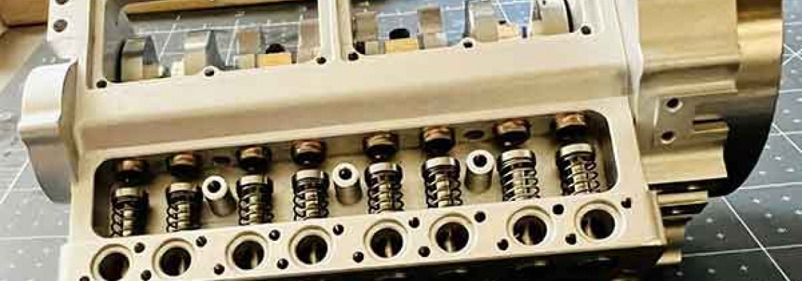
Using blue Loctite throughout the screw installation process is crucial to keep the screws from backing out of the valve tappets. Let the Loctite dry after screw installation, then clean the tappets of any remaining loctite before reinstalling them in the block. Every valve in the engine block has a corresponding number and location. When installing the valves, use tweezers and a pick to help install the springs, retainer, and clip.
8. Oil pump assembly
Dowel pins are no longer used in the driven oil pump gear. The oil pump will only malfunction if the dowel pin is present.
9. Water pump assembly
Use Loctite around the seal to keep the water pump front seal in place. Leaks can be avoided by applying a thin coating of RTV sealant to the water pump gasket or shim.
10. Pulley installation
Loctite is used to secure the pulleys in position. Verify that the two belts and the pulleys are in line. You can use a pen torch to apply heat to remove Loctite.
11. Trigger magnet installation
A vice might be used to install the trigger magnet in the pulley. It is crucial to face the magnet's coloured side outward in the direction of the Hall Effect sensor.
